Página de pruebas 4
Contents
- 1 ACA Module 3 LAB - Making Your Environment Highly Available
- 1.1 Task 1 - Inspect Your environment
- 1.2 Task 2 - Login to your Amazon EC2 instance
- 1.3 Task 3 - Install and Launch Your Web Server PHP Application
- 1.4 Task 4 - Create an Amazon Machine Image - AMI
- 1.5 Task 5 - Configure a Second Availability Zone
- 1.6 Task 6 - Create an Application Load Balancer
- 1.7 Task 7 - Create an Auto Scaling Group
- 1.8 Task 8 - Test the Application
- 1.9 Task 9 - Test High Availability
ACA Module 3 LAB - Making Your Environment Highly Available
https://labs.vocareum.com/main/main.php
Critical business systems should be deployed as Highly Available applications, meaning that they can remain operational even when some components fail. To achieve High Availability in AWS, it is recommended to run services across multiple Availability Zones.
Many AWS services are inherently highly available, such as Load Balancers, or can be configured for high availability, such as deploying Amazon EC2 instances in multiple Availability Zones.
In this lab, you will start with an application running on a single Amazon EC2 instance and will then convert it to be Highly Available.
Objectives:
After completing this lab, you will be able to:
- Create an image of an existing Amazon EC2 instance and use it to launch new instances.
- Expand an Amazon VPC to additional Availability Zones.
- Create VPC Subnets and Route Tables.
- Create an AWS NAT Gateway.
- Create a Load Balancer.
- Create an Auto Scaling group.
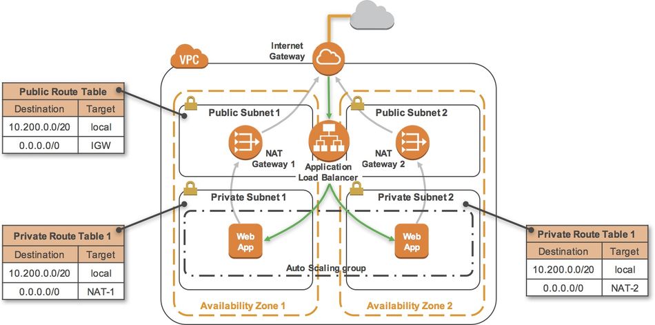
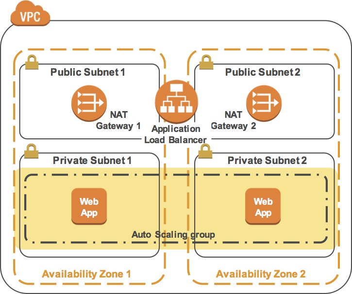
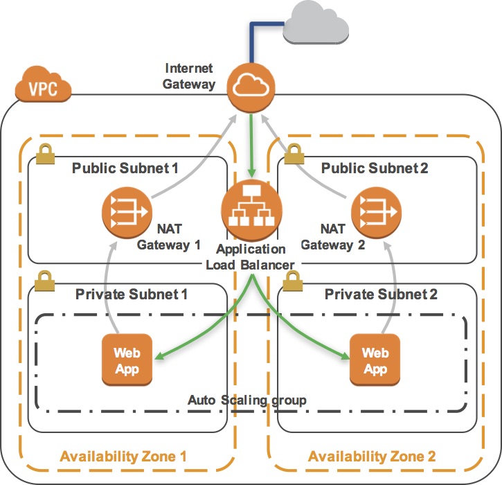
The final product of your lab will be this:
Task 1 - Inspect Your environment
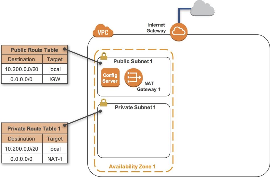
This lab begins with an environment already deployed via AWS CloudFormation including:
- An Amazon VPC
- A public subnet and a private subnet in one Availability Zone
- An Internet Gateway associated with the public subnet
- A NAT Gateway in the public subnet
- An Amazon EC2 instance in the public subnet
Task 1-1 - Inspect Your VPC
- On the AWS Management Console, on the Services menu, click VPC.
- In the left navigation pane, click Your VPCs.
- Here you can see the Lab VPC that has been created for you.
- IP range: In the IPv4 CIDR column, you can see a value of 10.200.0.0/20, which means this VPC includes 4,096 IPs between 10.200.0.0 and 10.200.15.255 (with some reserved and unusable).
- It is also attached to a Route Table and a Network ACL.
- This VPC also has a Tenancy of default, instances launched into this VPC will by default use shared tenancy hardware.
- Subnets: In the navigation pane, click Subnets.
- Here you can see the Public Subnet 1 subnet:
- In the VPC column, you can see that this subnet exists inside of Lab VPC
- IP range: In the IPv4 CIDR column, you can see a value of 10.200.0.0/24, which means this subnet includes the 256 IPs (5 of which are reserved and unusable) between 10.200.0.0 and 10.200.0.255.
- Availability Zone: In the Availability Zone column, you can see the Availability Zone in which this subnet resides.
- Click on the row containing Public Subnet 1 to reveal more details at the bottom of the page.
- Route Table: Click the Route Table tab in the lower half of the window.
- Here you can see details about the Routing for this subnet:
- Local traffic: The first entry specifies that traffic destined within the VPC's CIDR range (10.200.0.0/20) will be routed within the VPC (local).
- Internet Gateway: The second entry specifies that any traffic destined for the Internet (0.0.0.0/0) is routed to the Internet Gateway (igw-). This setting makes it a Public Subnet.
- In the left navigation pane, click Internet Gateways.
- Notice that an Internet Gateway is already associated with Lab VPC.
- ACL: Click the Network ACL tab in the lower half of the window.
- Here you can see the Network Access Control List (ACL) associated with the subnet. The rules currently permit ALL Traffic to flow in and out of the subnet, but they can be further restricted by using Security Groups.
- Security Groups: In the navigation pane, click Security Groups.
- Click Configuration Server SG.
- This is the security group used by the Configuration Server.
- Click the Inbound Rules tab in the lower half of the window.
- Here you can see that this Security Group only allows traffic via SSH (TCP port 22) and HTTP (TCP port 80).
- Click the Outbound Rules tab.
- Here you can see that this Security Group allows all outbound traffic.
Task 1-2 - Inspect Your Amazon EC2 Instance
In this task, you will inspect the Amazon EC2 instance that was launched for you.
- On the Services menu, click EC2.
- In the left navigation pane, click Instances.
- Here you can see that a Configuration Server is already running. In the Description tab in the lower half of the window, you can see the details of this instance, including:
- Public and private IP addresses
- Availability zone
- VPC
- Subnet
- Security Groups.
- In the Actions menu, click Instance Settings > View/Change User Data.
- Note that no User Data appears! This means that the instance has not yet been configured to run your web application. When launching an Amazon EC2 instance, you can provide a User Data script that is executed when the instance first starts and is used to configure the instance. However, in this lab you will configure the instance yourself!
- Click Cancel to close the User Data dialog box.
Task 2 - Login to your Amazon EC2 instance
- En este lab se descargó el archivo «labsuser.pem» de una forma particular debido a que el la genera la VPC and Instances de forma automática. Sabemos que este archivo «labsuser.pem» se optiene cuando se crea la Instance, podemos descargarlo y contiene la ssh key que permite autenticar la conexión entre nuestra computadora y la instance.
- Change the permissions on the key to be read only, by running this command:
chmod 400 labsuser.pem
- Luego para conectarnos desde el terminal:
ssh -i labsuser.pem ec2-user@<public-ip>
Task 3 - Install and Launch Your Web Server PHP Application
sudo yum -y update
This command installs an Apache web server (httpd) and the PHP language interpreter:
sudo yum -y install httpd php
This configures the Apache web server to automatically start when the instance starts:
sudo chkconfig httpd on
This downloads a zip file containing the PHP web application:
wget https://aws-tc-largeobjects.s3-us-west-2.amazonaws.com/CUR-TF-200-ACACAD/studentdownload/phpapp.zip
sudo unzip phpapp.zip -d /var/www/html/
This starts the Apache web server:
sudo service httpd start
Open a new web browser tab, paste the Public IP address for your instance in the address bar and hit Enter. The web application should appear and will display information about your location (actually, the location of your Amazon EC2 instance). This information is obtained from freegeoip.app.
Task 4 - Create an Amazon Machine Image - AMI
Now that your web application is configured on your instance, you will create an Amazon Machine Image (AMI) of it. An AMI is a copy of the disk volumes attached to an Amazon EC2 instance. When a new instance is launched from an AMI, the disk volumes will contain exactly the same data as the original instance.
This is an excellent way to clone instances to run an application on multiple instances, even across multiple Availability Zones.
In this task, you will create an AMI from your Amazon EC2 instance. You will later use this image to launch additional, fully-configured instances to provide a Highly Available solution.
- Return to the web browser tab showing the EC2 Management Console.
- Ensure that your Configuration Server is selected, and click Actions > Image > Create Image.
- You will see that a Root Volume is currently associated with the instance. This volume will be copied into the AMI.
- For Image name, type: Web application
- Leave other values at their default settings and click Create Image.
- Click Close.
- The AMI will be created in the background and you will use it in a later step. There is no need to wait while it is being created.
Task 5 - Configure a Second Availability Zone
To build a highly available application, it is a best practice to launch resources in multiple Availability Zones. Availability Zones are physically separate data centers (or groups of data centers) within the same Region. Running your applications across multiple Availability Zones will provide greater availability in case of failure within a data center.
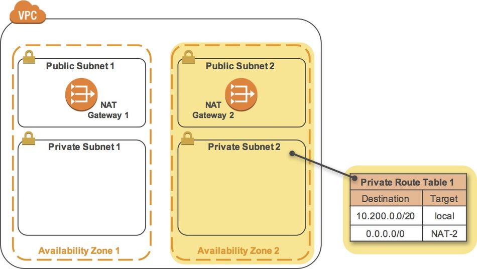
In this task, you will duplicate your network environment into a second Availability Zone. You will create:
- A second public subnet
- A second private subnet
- A second NAT Gateway
- A second private Route Table
Task 5-1 - Create a second Public Subnet
- On the Services menu, click VPC.
- In the left navigation pane, click Subnets.
- In the row for Public Subnet 1, take note of the value for Availability Zone. (You might need to scroll sideways to see it.)
- Note: The name of an Availability Zone consists of the Region name (eg us-west-2) plus a zone identifier (eg a). Together, this Availability Zone has a name of us-west-2a.
- Click Create Subnet. In the Create Subnet dialog box, configure the following:
- Name tag:
Public Subnet 2 - VPC: Lab VPC
- Availability Zone: Choose a different Availability Zone from the existing Subnet (for example, if it was a, then choose b).
- IPv4 CIDR block:
10.200.1.0/24
- This will create a second Subnet in a different Availability Zone, but still within Lab VPC. It will have an IP range between 10.200.1.0 and 10.200.1.255.
- Click Create.
- Name tag:
- Copy the Subnet ID to a text editor for later use, then click Close.
- It should look similar to: subnet-abcd1234
- Edit route table association:
- With Public Subnet 2 selected, click the Route Table tab in the lower half of the window. (Do not click the Route Tables link in the left navigation pane.)
- Here you can see that your new Subnet has been provided with a default Route Table, but this Route Table does not have a connection to your Internet gateway. You will change it to use the Public Route Table.
- Click Edit route table association.
- Try each Route Table ID in the list, selecting the one that shows a Target containing igw.
- Click Save then click Close.
- Because we have chosen a Route Table that has a connection to our Internet gateway, Public Subnet 2 is now a Public Subnet that can communicate directly with the Internet.
Task 5-2 - Create a Second Private Subnet
Your application will be deployed in private subnets for improved security. This prevents direct access from the Internet to the instances.
- Click Create subnet. In the Create Subnet dialog box, configure the following:
- Name tag: Private Subnet 2
- VPC: Lab VPC
- Availability Zone: Choose the same Availability Zone you just selected for Public Subnet 2.
- IPv4 CIDR block: 10.200.4.0/23
- Click Create and then click Close.
- The Subnet will have an IP range between 10.200.4.0 and 10.200.5.255.
Task 5-3 - Create a Second NAT Gateway
A NAT Gateway (Network Address Translation) is provisioned into a public Subnet and provides outbound Internet connectivity for resources in a private Subnet. Your web application requires connectivity to the Internet to retrieve geographic information, so you will need to route Internet-bound traffic through a NAT Gateway.
To remain Highly Available, your web application must be configured such that any problems in the first Availability Zone should not impact resources in the second Availability Zone, and vice versa. Therefore, you will create a second NAT Gateway in the second Availability Zone.
- In the left navigation pane, click NAT Gateways.
- Click Create NAT Gateway.
- For Subnet, enter the Subnet ID for Public Subnet 2 that you copied to a text editor earlier in the lab.
- Click Create New EIP.
- An Elastic IP Address (EIP) is a static IP address that will be associated with this NAT Gateway. The Elastic IP address will remain unchanged over the life of the NAT Gateway.
- Click Create a NAT Gateway, then click Close.
- You will now see two NAT Gateways.
- Tip: If you only see one, click the refresh icon in the top-right until the second one appears.
- The NAT Gateway that you just created will initially have a status of pending. Once it becomes available, you will see that it will have a private IP Address starting with 10.200.1.
- Copy the NAT Gateway ID show in the first column, starting with nat-. Paste it into a text document for use in the next task.
- You must now configure your network to use the second NAT Gateway.
Task 5-4 - Create a Second Private Route Table
A Route Table defines how traffic flows into and out of a Subnet. You will now create a Route Table for Private Subnet 2 that sends Internet-bound traffic through the NAT Gateway that you just created.
- In the navigation pane, click Route Tables.
- Click Create route table.
- In the Create route table dialog box, configure the following:
- Name tag: Private Route Table 2
- VPC: Lab VPC
- Click Create, then click Close.
- Highlight the Private Route Table 2 that you just created, and click the Routes tab in the lower half of the window.
- The Route Table currently only sends traffic within the VPC, as shown in the route table entry with the Target of local. You will now configure the Route Table to send Internet-bound traffic (identified with the wildcard 0.0.0.0/0) through the second NAT Gateway.
- Click Edit routes. Then Click Add route.
- For Destination, type: 0.0.0.0/0
- Click in the Target drop down list, and choose the NAT Gateway with the ID you copied earlier. (Check your text editor for the nat- ID you saved earlier.)
- Click Save routes, then click Close.
- You can now associate this Route Table (Private Route Table 2) with the second Private Subnet 2 that you created earlier.
- With Private Route Table 2 still selected, click the Subnet Associations tab at the bottom of the screen.
- Click Edit subnet associations.
- Select (tick) the checkbox beside Private Subnet 2.
- Click Save.
- Private Subnet 2 will now route Internet-bound traffic through the second NAT Gateway.
Task 6 - Create an Application Load Balancer
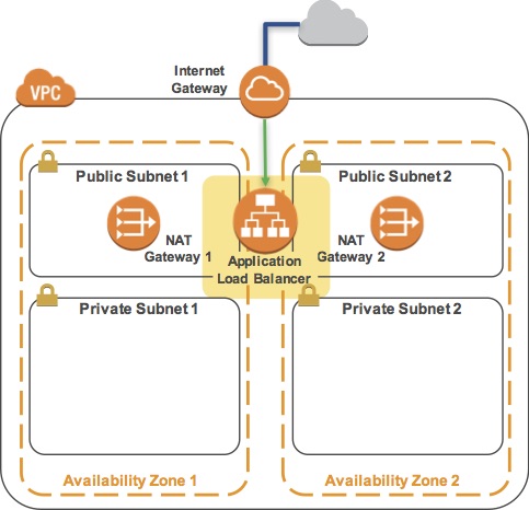
In this task, you will create an Application Load Balancer that distributes requests across multiple Amazon EC2 instances. This is a critical component of a Highly Available architecture because the Load Balancer performs health checks on instances and only sends requests to healthy instances.
You do not have any instances yet -- they will be created by the Auto Scaling group in the next task.
- On the Services menu, click EC2.
- In the left navigation pane, click Load Balancers (you might need to scroll down to find it).
- Click Create Load Balancer.
- Several types of Load Balancers are displayed. Read the descriptions of each type to understand their capabilities.
- Under Application Load Balancer, click Create.
- For Name, type: LB1
- Scroll down to the Availability Zones section.
- For VPC, select Lab VPC.
- You will now specify which subnets the Load Balancer should use. It will be an Internet-facing load balancer, so you will select both Public Subnets.
- Click the first displayed Availability Zone, then click the Public Subnet displayed underneath.
- Click the second displayed Availability Zone, then click the Public Subnet displayed underneath.
- You should now have two subnets selected: Public Subnet 1 and Public Subnet 2. (If not, go back and try the configuration again.)
- Click Next: Configure Security Settings.
- A warning is displayed, which recommends using HTTPS for improved security. This is good advice, but is not necessary for this lab.
- Click Next: Configure Security Groups.
- Select the Security Group with a Description of Security group for the web servers (and deselect any other security group).
- Note: This Security Group permits only HTTP incoming traffic, so it can be used on both the Load Balancer and the web servers.
- Click Next: Configure Routing.
- Target Groups define where to send traffic that comes into the Load Balancer. The Application Load Balancer can send traffic to multiple Target Groups based upon the URL of the incoming request. Your web application will use only one Target Group.
- For Name, type: Group1
- Click Advanced health check settings to expand it.
- The Application Load Balancer automatically performs Health Checks on all instances to ensure that they are healthy and are responding to requests. The default settings are recommended, but you will make them slightly faster for use in this lab.
- For Healthy threshold, type: 2
- For Interval, type: 10
- This means that the Health Check will be performed every 10 seconds and if the instance responds correctly twice in a row, it will be considered healthy.
- Click Next: Register Targets.
- Targets are instances that will respond to requests from the Load Balancer. You do not have any web application instances yet, so you can skip this step.
- Click Next: Review.
- Review the settings and click Create.
- Click Close.
- You can now create an Auto Scaling group to launch your Amazon EC2 instances.
Task 7 - Create an Auto Scaling Group
Auto Scaling is a service designed to launch or terminate Amazon EC2 instances automatically based on user-defined policies, schedules, and health checks. It also automatically distributes instances across multiple Availability Zones to make applications Highly Available.
In this task, you will create an Auto Scaling group that deploys Amazon EC2 instances across your Private Subnets. This is best practice security for deploying applications because instances in a private subnet cannot be accessed from the Internet. Instead, users will send requests to the Load Balancer, which will forward the requests to Amazon EC2 instances in the private subnets.
- In the left navigation pane, click Auto Scaling Groups (you might need to scroll down to find it).
- Click Create Auto Scaling group.
- Click Get started.
- A Launch Configuration defines what type of instances should be launched by Auto Scaling. The interface looks similar to launching an Amazon EC2 instance, but rather than launching an instance it stores the configuration for later use.
- You will configure the Launch Configuration to use the AMI that you created earlier. It contains a copy of the software that you installed on the Configuration Server.
- In the left navigation pane, click My AMIs.
- In the row for Web application, click Select.
- Accept the default (t2.micro) instance type and click Next: Configure details .
- For Name, type: Web-Configuration
- Click Next: Add Storage.
- You do not require additional storage on this instance, so keep the default settings.
- Click Next: Configure Security Group.
- Click Select an existing security group.
- Select the Security Group with a Description of Security group for the web servers.
- Click Review.
- You may receive a warning that you will not be able to connect to the instance via SSH. This is acceptable because the server configuration is already defined on the AMI and there is no need to login to the instance.
- Click Continue to dismiss the warning.
- Review the settings, then click Create launch configuration.
- When prompted, accept the vockey keypair, select the acknowledgement check box, then click Create launch configuration.
- You will now be prompted to create the Auto Scaling group. This includes defining the number of instances and where they should be launched.
- In the Create Auto Scaling Group page, configure the following settings:
- Group Name: Web application
- Group Size: Start with 2 instances
- Network: Lab VPC
- Subnet: Click in the box and select both Private Subnet 1 and Private Subnet 2
- Auto Scaling will automatically distribute the instances amongst the selected Subnets, with each Subnet in a different Availability Zone. This is excellent for maintaining High Availability because the application will survive the failure of an Availability Zone.
- Click the Advanced Details heading to expand it.
- Select (tick) the Load Balancing checkbox.
- Click in Target Groups, then select Group1.
- Click Next: Configure scaling policies.
- Ensure Keep this group at its initial size is selected.
- This configuration tells Auto Scaling to always maintain two instances in the Auto Scaling group. This is ideal for a Highly Available application because the application will continue to operate even if one instance fails. In such an event, Auto Scaling will automatically launch a replacement instance.
- Click Next: Configure Notifications.
- You will not be configuring any notifications.
- Click Next: Configure Tags.
- Tags placed on the Auto Scaling group can also automatically propagate to the instances launched by Auto Scaling.
- For Key, type: Name
- For Value, type: Web application
- Click Review.
- Review the settings, then click Create Auto Scaling group.
- Click Close.
- Your Auto Scaling group will initially show zero instances. This should soon update to two instances. (Click the refresh icon in the top-right to update the display.)
- Your application will soon be running across two Availability Zones and Auto Scaling will maintain that configuration even if an instance or Availability Zone fails.
Task 8 - Test the Application
In this task, you will confirm that your web application is running and you will test that it is highly available.
- In the left navigation pane, select Target Groups.
- Click the Targets tab in the lower half of the window.
- You should see two Registered instances. The Status column shows the results of the Load Balancer Health Check that is performed against the instances.
- Occasionally click the refresh icon in the top-right until the Status for both instances appears as healthy.
- If the status does not eventually change to healthy, ask your instructor for assistance in diagnosing the configuration. Hovering over the icon in the Status column will provide more information about the status.
- You will be testing the application by connecting to the Load Balancer, which will then send your request to one of the Amazon EC2 instances. You will need to retrieve the DNS Name of the Load Balancer.
- In the left navigation pane, click Load Balancers.
- In the Description tab in the lower half of the window, copy the DNS Name to your clipboard, but do not copy "(A Record)". It should be similar to: LB1-xxxx.elb.amazonaws.com
- Open a new web browser tab, paste the DNS Name from your clipboard and hit Enter.
- The Load Balancer forwarded your request to one of the Amazon EC2 instances. The Instance ID and Availability Zone are shown at the bottom of the web application.
- Reload the page in your web browser. You should notice that the Instance ID and Availability Zone sometimes changes between the two instances.
- The flow of information when displaying this web application is:
- You sent the request to the Load Balancer, which resides in the public subnets that are connected to the Internet.
- The Load Balancer chose one of the Amazon EC2 instances that reside in the private subnets and forwarded the request to it.
- The Amazon EC2 instance requested geographic information from freegeoip.app. This request went out to the Internet through the NAT Gateway in the same Availability Zone as the instance.
- The Amazon EC2 instance then returned the web page to the Load Balancer, which returned it to your web browser.
Task 9 - Test High Availability
Your application has been configured to be Highly Available. This can be proven by stopping one of the Amazon EC2 instances.
- Return to the EC2 Management Console tab in your web browser (but do not close the web application tab - you will return to it soon).
- In the left navigation pane, click Instances.
- First, you do not require the Configuration Server any longer, so it can be terminated.
- Select the Configuration Server.
- Click Actions > Instance State > Terminate, then click Yes, Terminate.
- Next, stop one of the Web application instances to simulate a failure.
- Select one of the instances named Web application (it does not matter which one you select).
- Click Actions > Instance State > Stop, then click Yes, Stop.
- In a short time, the Load Balancer will notice that the instance is not responding and will automatically route all requests to the remaining instance.
- Return to the Web application tab in your web browser and reload the page several times.
- You should notice that the Availability Zone shown at the bottom of the page stays the same. Even though an instance has failed, your application remains available.
- After a few minutes, Auto Scaling will also notice the instance failure. It has been configured to keep two instances running, so Auto Scaling will automatically launch a replacement instance.
- Return to the EC2 Management Console tab in your web browser. Click the refresh icon in the top-right occasionally until a new Amazon EC2 instance appears.
- After a few minutes, the Health Check for the new instance should become healthy and the Load Balancer will continue sending traffic between two Availability Zones. You can reload your Web application tab to see this happening.
- This demonstrates that your application is now Highly Available.
