Difference between revisions of "Systems Analysis & Design"
Adelo Vieira (talk | contribs) |
Adelo Vieira (talk | contribs) (→A use case diagram) |
||
| Line 35: | Line 35: | ||
'''UML symbols used to model these concepts:''' | '''UML symbols used to model these concepts:''' | ||
| + | |||
| + | A use case: an ellipse labelled with the name of the use case. Conventionally we start each use case name with a verb to make the point that use cases represent processes. So we have 'Maintain customer list' rather than 'Customer list', 'Handle enquiries' rather than 'Enquiries'. | ||
| + | |||
| + | [[File:use_case.png|950px|thumb|center|Use case]] | ||
| + | |||
| + | An actor: a stick figure labelled with the name of the actor. We capitalize actor names so that they are easy to identify as such (e.g. Administrator, Receptionist). The stick figure icon is used even when the actor is non-human, e.g. another computer system or an organization. | ||
| + | |||
| + | [[File:actor.png|950px|thumb|center|Actor]] | ||
| + | |||
| + | A use case relationship: a line linking an actor to a use case. The line shows us which actors are associated with which use cases. This relationship is also known as a communication association. | ||
| + | |||
| + | [[File:use_case_relationship.png|950px|thumb|center|Use case relationship]] | ||
| + | |||
| + | The boundary: a line drawn round the use cases to separate them from the actors and to delineate the area of interest. Can be labelled to indicate the diagram domain. The boundary is often omitted. | ||
| + | |||
| + | [[File:boundary.png|950px|thumb|center|Boundary]] | ||
Revision as of 13:50, 20 February 2018
Contents
Software
Software required for this course: Visual Paradigm (Community Edition) You must register but it is a free trial version
Link to Visual Pardigm community edition (free): http://www.visual-paradigm.com/download/community.jsp
Xtra-vision express URL (Importante: revisar esto para la próxima clase)
Click https://xtra-vision.ie/how-it-works/ link to open resource.
UML
The UML (Unified Modeling Language) is an international industry standard graphical notation for describing software analysis and designs.
Fundamental UML models
There are five fundamental UML models:
- Use case model
- Class model,
- Sequence model
- State model
- Activity diagrams
Use case model
The use case model consists of:
- A use case diagram,
- A set of use case descriptions,
- A set of actor descriptions, and
- A set of scenarios.
A use case diagram
The use case diagram models the problem domain graphically using four concepts:
- The use case,
- The actor,
- The relationship link, and
- The boundary.
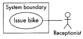
UML symbols used to model these concepts:
A use case: an ellipse labelled with the name of the use case. Conventionally we start each use case name with a verb to make the point that use cases represent processes. So we have 'Maintain customer list' rather than 'Customer list', 'Handle enquiries' rather than 'Enquiries'.
An actor: a stick figure labelled with the name of the actor. We capitalize actor names so that they are easy to identify as such (e.g. Administrator, Receptionist). The stick figure icon is used even when the actor is non-human, e.g. another computer system or an organization.
A use case relationship: a line linking an actor to a use case. The line shows us which actors are associated with which use cases. This relationship is also known as a communication association.
The boundary: a line drawn round the use cases to separate them from the actors and to delineate the area of interest. Can be labelled to indicate the diagram domain. The boundary is often omitted.


